Modelling
The
architectural design stage occurs early on in the software development
process. At this stage little or no code will have been written. It is
therefore difficult to use traditional usability techniques directly, as
these rely on having access to at least a partly finished product. To allow
the usability of a proposed design to be assessed, we construct a model of
the system. Modelling is a popular technique across many engineering
disciplines for determining properties of a system or artefact before the
final version is produced. In this way refinements to the design can be
made more quickly and cheaply than would be the case if the whole product
has to be developed before iteration.
Message Sequence Charts
Constructing
a model of a software system at the architectural level involves specifying
interactions between different components of the system, and also
interactions between the user and the system. We have found that UML style
Message Sequence Charts (MSCs) provide an intuitive notation for specifying
these interactions at an appropriate level of abstraction. During the
STATUS project we have developed tool support for MSCs within the Labelled
Transition System Analyser (LTSA) tool. Using this tool, architectural
models can be specified graphically (see Deliverable 3.3 for
details).
A full
MSC specification consists of two types of diagram. A basic Message
Sequence Chart (bMSC) specifies the interactions that occur in a particular
scenario. For example, for a web application that provides a web-based
email system, a possible scenario is that the user tries to log in to the
system, supplying a particular name and password, and is authenticated
correctly be the server. The bMSC in Figure 3 shows the trace of actions from
a user being enabled to use the system by the administrator, through the
user logging in to the system and reading a message before logging out
again.
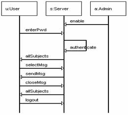
Figure 3. bMSC showing interaction between users and a webmail
system
Individual
scenarios, described as bMSCs, can be sequenced to describe the behaviour
of a system as a whole. The trace shown in Figure 3 can be factored into a set of
smaller bMSCs describing individual sub-tasks, such as logging in,
selecting a message etc. The order that these sub-tasks need to be
performed in to achieve an overall goal can then be specified using a
high-level Message Sequence Chart (hMSC), as shown in Figure 4. Our tool supports
graphical specification of hMSCs as well as bMSCs.
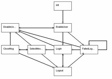
Figure
4. hMSC showing ordering of
scenarios for webmail system
State
models in the form of Labelled Transition Systems (LTSs) can be generated
automatically from an MSC specification using a synthesis algorithm. We
have incorporated this into our tool. We use LTSs to form the basis of the
behaviour models that drive our simulation and animation approaches. Figure 5
shows a graphical representation of the LTS (exported from our tool)
generated from the MSC specification given above.
Figure
5 : Synthesised LTS for server component
Simulation
and animation techniques have been used successfully to allow interaction
between users and models. Animation techniques allow a view of the model to
be presented in terms that are easily understood by the user. In the STATUS
project we have been focussing on the domain of e-commerce applications and
have developed animation techniques that allow users to interact with
models through a web interface. By presenting a series of web pages, users
can step through the different states of the model as if they were
interacting with the finished system.

Figure
6 : Screen animating webmail system model
Usability
experiments can be conducted using traditional techniques such as
interviews, questionnaires or expert observation, but with users
interacting with the simulation rather than the final product. This allows
feedback regarding the usability of the system to be used as an input to
design decisions early in the development process. At this stage it is
relatively inexpensive to make changes to the architecture of the system. The
effect of making an architectural change is reflected immediately in the
simulation.
The
tools that we have developed allow for rapid prototyping and rapid
iteration of designs. As MSC specifications can be manipulated graphically
within the tool, changes can be made quickly. This makes it possible to
make changes to the model’s behaviour, and to re-run the simulation,
within the scope of a user-centred design session.
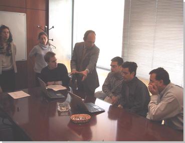
Figure
7 : User centred
design session
In the
requirements gathering stage of software design, various goals that the
user wants to achieve using a software system can be specified. We have
worked on methods for refining these goals, and expressing them in terms of
fluents. We have then used sets of fluents as the basis for
specifying visualisation rules. Fluents describe aspects of the state of a
system that may change over time. For example, we define a fluent LoggedIn, in relation to the model of
the webmail system, as follows:
fluent LoggedIn = <authenticate, {logout,
disable}>
This
specifies that the fluent LoggedIn becomes true after the authenticate
action occurs, and remains true until either the user logs out, or is
disabled by the administrator. We then
specify visualisation rules in terms of these fluents, using the truth or
falsehood of the fluents to predicate whether various parts of the
visualisation are displayed at a particular state of the system.
The
following example shows the visualisation rule for the screen shown in Figure 6 (in reality we use an XML
document for this specification, but this is abbreviated in the figure for
clarity). When the user is not logged in, the page that they see in their
web browser will feature login and password boxes, with a submission
button.
showwhen
not LoggedIn
display
<!— HTML for username, password
boxes -->
table tr
td input type="text" name="userid"
td input
type="password" name="pwd"
td
button enterPwd
|
|
As
users explore the model, different fluents become true and false and the
visualisation changes accordingly. The abstraction of the visualisation
rules in terms of fluents makes it easy to modify the specification. It
also relates the specification of the visual aspects to the user goals
defined for the system.
We have
supported these visualisation techniques within the LTSA tool. We have used
standard Internet technologies, so users can interact with the model using
a standard web browser that connects to our tool over the Internet.
Once a
design has been assessed for usability, we may want to refine it in order
to address any issues that have been uncovered. This may be achieved by
applying one of the usability patterns identified as part of the
STATUS project (see Deliverable 3.4.).
Our usability patterns describe architectural considerations, which may
have two aspects: the structure of the system and the interaction between
components. In some cases applying a pattern requires the alteration of one
of these aspects independently of the other. For example, if a traditional
client-server web application is adapted to work with mobile devices, it is
likely that the set of interactions possible between the user and the
system will be required to be the same for the different types of device,
however changes need to be made to the structure. In other cases a
different set of interactions may need to be introduced for an existing
structure.
We have
developed modelling techniques that separate behaviour from structure, and
allow these to be specified and modified independently of one another. This
is done by using the MSC notation together with the Darwin ADL. This is
particularly helpful in applying changes to architectures during the
refinement process without having to rewrite the whole model. This gives us
the final step in our design iteration process.
|